
Managing FortiSwitches using a Layer 3 FortiLink connection
- Matt Sherif

- May 3, 2020
- 5 min read
A customer recently reached out to me to ask about a specific design they had in mind. Last year they had purchased a pair of switches for their core / distribution layer, but since they've been introduced to Fortinet and the FortiLink management, they wanted to replace the access/edge layer with FortiSwitches since the management is integrated into the FortiGate.
The only snag is, the customer's design required the core switches sit between the FortiGate and the access FortiSwitches. It's important to note that traffic handled in this fashion is not inspected by the FortiGate, so be aware of the disadvantages of this approach before deploying this type of architecture. Typical FortiLink is similar to LLDP in how it operates, that is it cannot traverse multiple switches, it can only go over one physical segment of a network. In this scenario, the core switches pose a problem as the management frames would not be passed through the core to the FortiSwitches. The proposed topology looks like this:

I knew that a layer 3 FortiLink is possible, but I wasn't sure what that would look like from a deployment perspective. And I felt this would be a good topic to write up.
Assumptions
FortiGate running 6.2.3 or later
FortiSwitch running 6.0.x or later
VLANs/Virtual VLAN Interfaces (layer3) are already created on the 3rd party switch - if not, do so now. As in this scenario the Core/Distribution layer will be handling internal routing. I am using a Brocade ICX 7150-C12P as my 3rd party switch. My VLANs and VE (router-interfaces) have already been created.
Ok, now that we got this out of the way, let's get to it!
Creating a FortiLink interface on the FortiGate
In this section we're configuring the following section:

Regardless of how we go about managing our FortiSwitches, we need to create a FortiLink interface before we can start adding switches. In 6.2.x and above you can conveniently do this from WiFi & Switch Controller > FortiLink.

From here you can create the FortiLink necessary to manage the FortiSwitches.
NOTE:The network that the FortiLink interface is a member of will not permit creating a policy out to the internet with the FortiLink interface as the source interface, so I am also creating a VLAN on that interface that will be routeable.

To summarize, at this point we have created the FortiLink interface for FortiSwitch management, as well as a VLAN interface that user traffic will traverse.
Configuring the FortiSwitch for 3rd party management:
Now that we have a FortiLink interface, we need to configure our FortiSwitches and get them ready for management. I'll cover the configuration of one, the rest can be done with the same process.

First I am going to power up my FortiSwitch - in this scenario I am using a FortiSwitch FS-108E-FPOE. I will get my terminal emulator ready and configure it for the following settings:
Baud rate: 115200
Data bits: 8
Parity: None
Stop bits: 1
Flow control: None
I will then plug in the console cable into the switch, a few taps of enter you should see the login prompt. It is best if you factory reset the switch by issuing the execute factoryreset command. Once this is done you can log in with 'admin' and no password. Be sure to change the password on first logon.
Next I will plug port1 of the FortiSwitch into port 2 of the 3rd party switch.
To manually configure the FortiSwitch to FortiLink mode from the console enter the following:
config system global
    set switch-mgmt-mode fortilink
end
# We also need to set the IP of the switch so it can be managed
config system interface
    edit internal
        set mode static
        set ip 192.168.51.2/24
    next
end
# configuring default gateway
config router static
    edit 0
        set dst 0.0.0.0/0
        set gateway 192.168.51.1
        set device internal
    next
end
With the above you should be able to ping the FortiLink IP address we set earlier.
You have two choices of discovery, static and DHCP we will cover both in this article.
Option A: Static discovery:
Static discovery is just that, you configure the FortiSwitch with the IP address of the FortiGate. The advantage is you don't have any additional configuration, but the drawback is that the FortiGate's FortiLink IP address needs to be configured on every top-layer switch being managed in Layer 3 FortiLink. NOTE: FortiSwitches connected downstream of the first FortiSwitch do not need additional configuration.
Static discovery is configured as follows:
config switch-controller global
    set ac-discovery-type static
    # configure FortiLink IP target
    config ac-list
        edit 0
            set ipv4-address 192.168.50.1
        next
    end
end
Option B: DHCP Discovery
DHCP Discovery relies on a DHCP option being configured that tells the FortiSwitch where it's controller is. By default this is DHCP option 138.
To configure a FortiSwitch for DHCP Discovery enter the following commands:
config switch-controller global
    set ac-discovery-type dhcp
    set dhcp-option-code 138
end
Configuring upstream ports for L3 FortiLink
Finally we need to configure the upstream interface we plugged in earlier (port1) to enable Layer 3 FortiLink mode:
config switch interface
    edit port1
        set fortilink-l3-mode enable
    next
end
NOTE: This can also be a Link Aggregation Group, you will need to configure the LAG prior to issuing the "set fortilink-l3-mode enable"
Upon issuing this command you should see the switch appear on the FortiGate for authorization:

Authorize the FortiSwitch, once it connects move on to configuring VLANs.
IMPORTANT: At this stage I could not get the switch to connect, it remained offline after authorization. After troubleshooting a bit, I did a get system status thinking it was a code version issue, and I noted the date was Jan 1st 1970 it was at this time I realized the FortiGate would not accept the connection because it was too large a time drift. If you run into this issue, you need to configure the FortiSwitch to use the FortiGate as an NTP server (It automatically listens for NTP on the FortiLink interface as of 6.2.x)
config system ntp
    set allow-unsync-source enable
        config ntpserver
            edit 1
                set server "192.168.50.1"
            next
        end
    set ntpsync enable
    set source-ip 192.168.51.2
end
The FortiGate should connect once the time synchronization is enabled on the FortiSwitch.
Configuring VLANs
Typically when you configure a VLAN on a FortiSwitch/FortiGate you are counting on the FortiGate being the "gateway/router" for that VLAN. In this case, our 3rd party switch is handling all internal routing so we will configure the VLANs but assign a 0.0.0.0/0.0.0.0 IP address to each of them. Be mindful of your VLAN segments and document where they are used, what they are for, and the rationale for the approach, as you might end up in a situation thinking to yourself "why did I do this?" later on down the road.
I will configure VLAN 85 on port 7 and 101 on port 8 of our FortiSwitch. These are the steps used:
Navigate to WiFi & Switch Controller > FortiSwitch VLANs
Click 'Create New'
Input the necessary information for the VLAN
Click 'OK'
Repeat for any other VLANs you may have

This can be done via CLI as well:
config system interface
    edit "INTERNAL_WLAN"
        set description "ASM Internal Wireless"
        set device-identification enable
        set role lan
        set interface "asm.ftl" # NOTE: this is your FortiLink interface
        set vlanid 85
    next
Once you've created the VLANs assign VLAN 85 to Port7 and 101 to Port8 on the FortiSwitch via WiFi & SwitchController > FortiSwitch Ports

Once these are assigned we can move on to validation.
One last thing we need to do to ensure traffic passes is to create a policy allowing traffic to come from the "LAN" VLAN we created earlier, adjust your settings accordingly.

Validating the settings
Depending on your network, you probably have a DHCP server providing IPs for these VLANs that we just configured. you will want to make sure your 3rd party switch has the proper DHCP forwarders configured for their respective VLANs. For this test I configured the IP addresses manually,
Port7 VLAN 85:

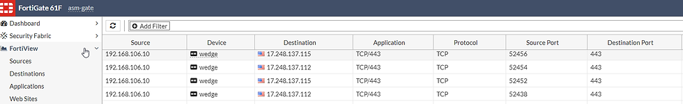
A quick look in FortiView > All Sessions shows us the sessions from this device:

Port8 VLAN 101:

A quick look in FortiView > All Sessions shows us the sessions from this device:
And that's it! In this article I showed you how to configure a Layer 3 FortiLink and manage your FortiSwitches over it. I hope this is helpful and thank you for reading!


Comments